NVIDIA GPU 架构:SP、SM 与 LSU 工作原理详解
本文整理自 NVIDIA 开发者论坛的两个讨论帖,重点探讨 SM 内部功能执行单元(FMA / LSU 等)的调度模型,以及 Ampere 架构中 LSU(Load/Store Unit)的详细工作机制。以下内容主要来自 NVIDIA 工程师 Greg 以及资深版主 Robert Crovella 的回答。
功能执行单元与 Warp-wide 调度
GPU 中所有指令的调度都以 warp(32 个 thread) 为粒度。SM 内的每一类功能执行单元(functional unit)——包括 FMA 单元(即 CUDA Core)、LSU(LD/ST Unit)、Tensor Core 等——每个单元每周期只处理 1 条指令、1 个 thread。因此,要在单个时钟周期内完成一条 warp-wide 指令(涵盖 32 个 thread),就需要 32 个同类功能单元并行工作。
以浮点乘加指令(FMUL/FMA)为例:如果希望一条 FMUL 在 1 个周期内完成整个 warp 的处理,就需要 32 个 FMA 单元同时工作,每个 FMA 单元负责 1 个 thread 的那一条指令。如果某个 SM sub-partition 只有 16 个 FMA 单元,那么一条 warp-wide 的 FMUL 就需要 2 个周期才能完全 issue。
LSU 遵循完全相同的逻辑。一条 warp-wide 的 Load/Store 指令(如 LDG、STG)同样需要 32 个 LSU 单元来支撑单周期 issue。如果 SM sub-partition 中 LSU 数量不足 32 个,那么该指令的 issue 就需要跨越多个周期。这里的 issue 是指指令进入 LSU pipeline 的 front end,后续还有地址 coalescing、cache 访问等流水线阶段。
Tensor Core 是一个例外——它的调度粒度与上述逻辑不同,单个 Tensor Core 在单周期内可以处理更大的矩阵片段,不遵循 “1 指令/1 thread/1 cycle” 的模型。
SM 子分区与 Warp Scheduler
在 Ampere 等现代架构中,一个 SM 被划分为若干 sub-partition(processing block)。每个 sub-partition 拥有自己的 Warp Scheduler、register file、以及一组 functional unit。以 Ampere 的 A100 为例,一个 SM 包含 4 个 sub-partition,因此有 4 个 Warp Scheduler,每个 sub-partition 每周期可以 issue 1 条指令,整个 SM 的算术指令吞吐峰值为 4 IPC。
然而,内存相关指令走的是另一条路径。所有 sub-partition issue 的 Load/Store 指令都汇集到 SM 级别的 MIO(Memory I/O)单元,而 MIO 每周期只能向 LSU pipeline 发送 1 条指令。这意味着即便 4 个 Warp Scheduler 都在 issue 内存指令,最终能进入 LSU pipeline 的也只有 1 条/周期——这是整个 SM 的内存指令 IPC 瓶颈所在,从 4 IPC 降至 1 IPC。
LSU 管线的工作流程
从 Warp Scheduler 到 LSU Pipeline
当一个 warp 准备执行 Load/Store 指令时,Warp Scheduler 将该指令送入 MIO instruction queue(一个 shallow queue)。在指令从 MIOC(MIO Controller)dispatch 之前,必须等到所有 register operand 都已从 register file 中读取完毕。读取完成后,指令进入 ready 状态,随后被 MIO 以每周期 1 条的速率 dispatch 到 LSU pipeline。
整个过程是异步的:指令一旦被 dispatch 到 LSU pipeline,该 warp 可以继续执行后续不依赖本次 Load/Store 结果的指令。只有当后续指令需要使用 Load 返回的数据时,该 warp 才会因 register 未就绪而 stall。
LSU Front End 与 Back Pressure 机制
Robert Crovella 强调,LSU 的 front end 并没有一个固定大小的 request queue。在理想情况下,LSU 可以持续以每周期 1 条指令(1 op/thread/clock)的速率接受新请求,不存在队列积压。
然而 LSU 只是 memory pipe 的 front end,它后面连接着 L1 cache、L2 cache、DRAM controller 等一系列硬件。当下游出现拥塞(例如大量 non-coalesced 访问导致 transaction 数量暴增),back pressure 信号会沿 pipeline 反向传播,最终以一种 on/off signal 的形式关闭 LSU 的入口——此时 LSU 立即停止接受新请求,后续的内存指令会引发 stall。这种 stall 既不是典型的 data dependency stall,也不一定是 register reservation stall,其具体分类在 NVIDIA 的公开文档中并没有详细说明。
Scoreboard 与寄存器复用
指令进入 LSU pipeline 后,编译器可以选择两种 scoreboard 更新策略。一种是在 MIO 将指令 dispatch 到 LSU 后立即释放 scoreboard,允许该 register 被后续指令写入新值——此时 register 中的地址数据已经被 LSU 读走,不再需要保留。另一种是等到 Load 指令的数据真正返回(retire)后才释放 scoreboard,确保更强的顺序保证。
据 Scott Gray 在 maxas wiki 中的观察,Read Dependency Barrier 的延迟大约为 20 个 clock——这是指令从 issue 到进入 in-flight 状态所需的时间,而完整的 Load 指令可能需要更多的 clock 才能返回数据。
如果一个 warp 执行到某条指令时,所依赖的 register 还未就绪(scoreboard 未释放),该 warp 就会进入 long scoreboard stall。此时 Warp Scheduler 会切换到其他 eligible warp 继续执行,直到该 warp 的 scoreboard 解除为止。
Wavefront 与地址合并
地址合并(Coalescing)
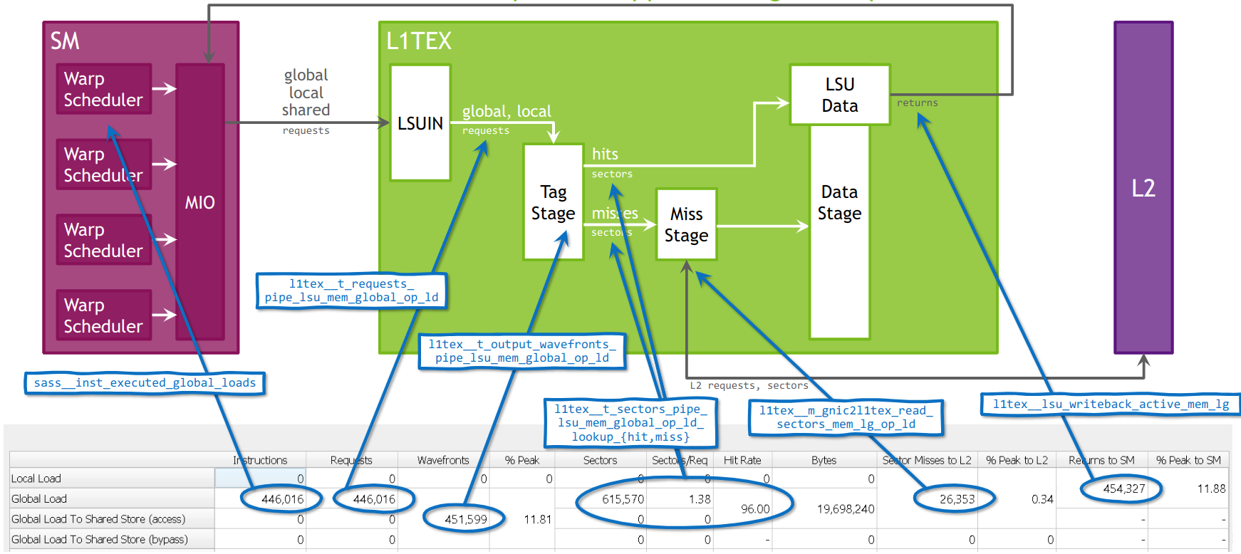
LSU pipeline 接收到一条 warp-wide 的 Load/Store 指令后,会将其 dispatch 到 shared memory pipe 或 tagged pipe(L1TEX)。在 tagged pipe 中,LSU 为 warp 中每个 thread 计算 cache tag(即地址所在的 32-byte sector),然后将落在同一 sector 内的 thread 合并为一个 wavefront。每个 wavefront 代表一次对 L1 cache 的访问请求。
在 GV100 及后续架构上,L1TEX 的 tag stage 每周期可以 resolve 4 sets × 4 sectors。如果单个 wavefront 无法覆盖所有 thread(即地址分散在超过 4 个 set 的 sector 中),LSU 会继续在 tag stage 生成新的 wavefront,每周期生成一个,直到该指令的所有 thread 都被处理完毕。
合并效率对吞吐的影响
Coalescing 的程度直接决定了 LSU pipeline 的实际吞吐。以 32-bit Load 为例:如果 warp 中 32 个 thread 访问连续的 4-byte 地址(总计 128 字节,覆盖 4 个 sector),那么仅需 1 个 t-stage wavefront 加上 4 个 miss-stage wavefront 就能完成——这是最理想的情况。
反过来,如果一条 Store 指令的 32 个 thread 分别写入 32 个不同的 sector(完全离散的地址),就会生成 32 个 wavefront,每个 wavefront 处理 1 个 sector。由于 wavefront 每周期只能生成 1 个,这条指令将独占 tag stage 长达 32 个周期,严重降低有效吞吐。
这也正是 coalesced 访问与 non-coalesced 访问之间的本质差异:前者用少量 transaction 完成请求(高效率),后者产生大量 transaction(低效率),并可能触发前述的下游 back pressure 机制。
Load 与 Store 的异同
Load 和 Store 指令在 LSU pipeline 中的 coalescing 流程是一致的,区别在于后续阶段。Load 指令在 L1 cache 响应后,LSU 从每个 sector 中提取对应数据写入各 thread 的目标 register,然后更新 scoreboard 通知 warp 数据就绪。Store 指令则是 fire-and-forget 操作:数据和地址被送入 write pipeline 后,source register 很快就可以被释放,不必等到写操作真正完成。
术语表
| 术语 | 说明 |
|---|---|
| SM (Streaming Multiprocessor) | GPU 核心执行单元,包含 Warp Scheduler、functional unit、register file、shared memory / L1 cache 等 |
| SP (Streaming Processor) / CUDA Core | SM 内部的算术 functional unit,每个单元每周期处理 1 条指令、1 个 thread |
| sub-partition (processing block) | SM 的子分区,每个拥有独立的 Warp Scheduler、register file 和一组 functional unit |
| Warp Scheduler | 每个 sub-partition 中的指令调度器,每周期从 eligible warp 中选择一个并 issue 1 条指令 |
| warp | 32 个 thread 的集合,是 GPU 调度和执行的最小粒度 |
| issue | Warp Scheduler 将指令发送到对应 functional unit 的动作 |
| dispatch | MIO Controller 将指令从 instruction queue 发送到 LSU pipeline 的动作 |
| IPC (Instructions Per Cycle) | 每周期指令吞吐,SM 算术峰值为 4 IPC,内存指令受 MIO 限制为 1 IPC |
| functional unit | SM 内的执行单元统称,包括 FMA unit、INT unit、LSU、Tensor Core、SFU 等 |
| FMA (Fused Multiply-Add) | 浮点乘加单元,即通常所说的 CUDA Core |
| LSU (Load/Store Unit) | 执行内存访问指令(LDG/STG/LDS/STS 等)的 functional unit |
| MIO (Memory I/O) | SM 级别的内存指令控制单元,汇集所有 sub-partition 的 Load/Store 指令,每周期向 LSU pipeline dispatch 1 条 |
| MIOC (MIO Controller) | MIO 的控制器,负责从 instruction queue 中取出 ready 指令并 dispatch |
| register file | 寄存器文件,每个 sub-partition 拥有独立的 register file,存放 thread 的局部数据 |
| register operand | 指令的寄存器操作数,dispatch 前必须从 register file 读取完毕 |
| scoreboard | 记录 register 依赖关系的硬件结构,防止 RAW(Read After Write)冒险 |
| long scoreboard stall | warp 因等待 register 数据就绪(如 Load 未返回)而进入的长延迟 stall |
| Read Dependency Barrier | 读依赖屏障,约 20 clock 延迟,指令从 issue 到进入 in-flight 状态的时间 |
| eligible warp | 所有操作数就绪、无 stall 的 warp,可被 Warp Scheduler 选中执行 |
| pipeline | 流水线,指令按阶段依次通过的硬件通路 |
| front end | pipeline 的前端/入口阶段 |
| back pressure | 下游硬件拥塞时,向上游发送的反压信号,导致 front end 停止接受新请求 |
| stall | 流水线停顿,warp 因某种原因无法继续执行,类似 CPU pipeline 中的 bubble |
| bubble | CPU pipeline 中因 hazard 插入的空操作周期,GPU 中对应 stall,通过 warp 切换实现 latency hiding |
| memory pipe | 内存访问硬件通路,包括 LSU(front end)、L1/L2 cache、DRAM controller 等 |
| L1TEX | L1 Texture/Data cache,处理 global memory 和 texture 访问的缓存子系统 |
| tag stage (t-stage) | L1TEX pipeline 中计算 cache tag、进行地址分组的阶段 |
| miss stage | L1TEX pipeline 中处理 cache miss 的阶段 |
| coalescing | 地址合并,将 warp 中多个 thread 的内存请求按 sector 合并以减少 transaction 数 |
| sector | 32-byte 的 cache 数据单元,是 L1 cache 访问的最小粒度 |
| wavefront | LSU 在 tag stage 中将同一 sector 的 thread 合并后生成的一次 cache 访问请求,每周期生成 1 个 |
| transaction | 一次实际的 cache/memory 数据传输操作 |
| coalesced / non-coalesced | 合并/非合并访问,前者 transaction 少(高效),后者 transaction 多(低效)可触发 back pressure |
| in-flight | 指令已 issue 但尚未 retire(完成),正在 pipeline 中执行 |
| retire | 指令执行完毕,结果写回 register file 或 cache |
| fire-and-forget | Store 指令的执行模式:数据送入 write pipeline 后 source register 即可释放,不等待写完成 |
| latency hiding | 延迟隐藏,GPU 通过大量 warp 并发,在某 warp stall 时切换到其他 eligible warp 继续执行 |
参考资料
Enjoy Reading This Article?
Here are some more articles you might like to read next: